
Thinking about Final Project, vol. 02

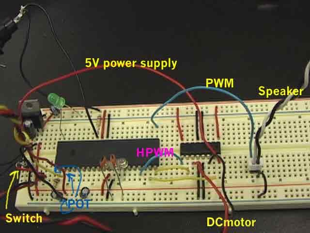
'set m-sensor into AN0
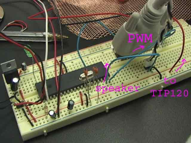
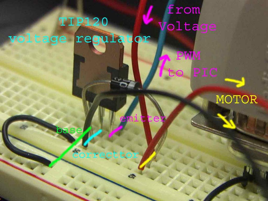
'set motor PWM into PORTD.1
'set speaker PWM into PORTD.0
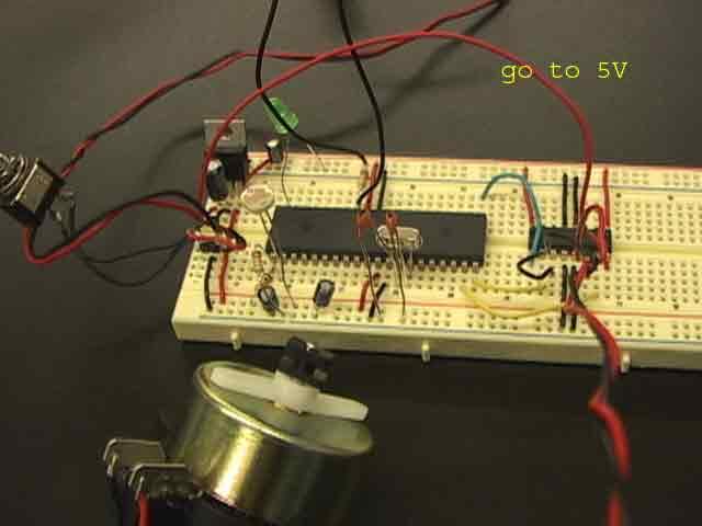
' OSC=Oscirator 4mhz
' It's not necessary but recommended
DEFINE OSC 4
start:
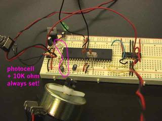
'Analog definifition
DEFINE ADC_BITS 10
' Set number of bits in result
DEFINE ADC_CLOCK 3
' Set clock source (3=rc)
DEFINE ADC_SAMPLEUS 10
' Set sampling time in uS
' Usually 50 but 10 or 50 not so much different
' Create variable to store result
'motor value, sound value
ADCvar VAR word
motorVal VAR byte
soundVal VAR byte
' Set PORTA to all input
TRISA = %11111111
' Set PORTA analog and right justify result
ADCON1 = %10000010
'set Lighting Trigger OUTPUT into portb.7
'set LED of FAN OUTPUT into portb.6
OUTPUT portb.7
OUTPUT portb.6
main:
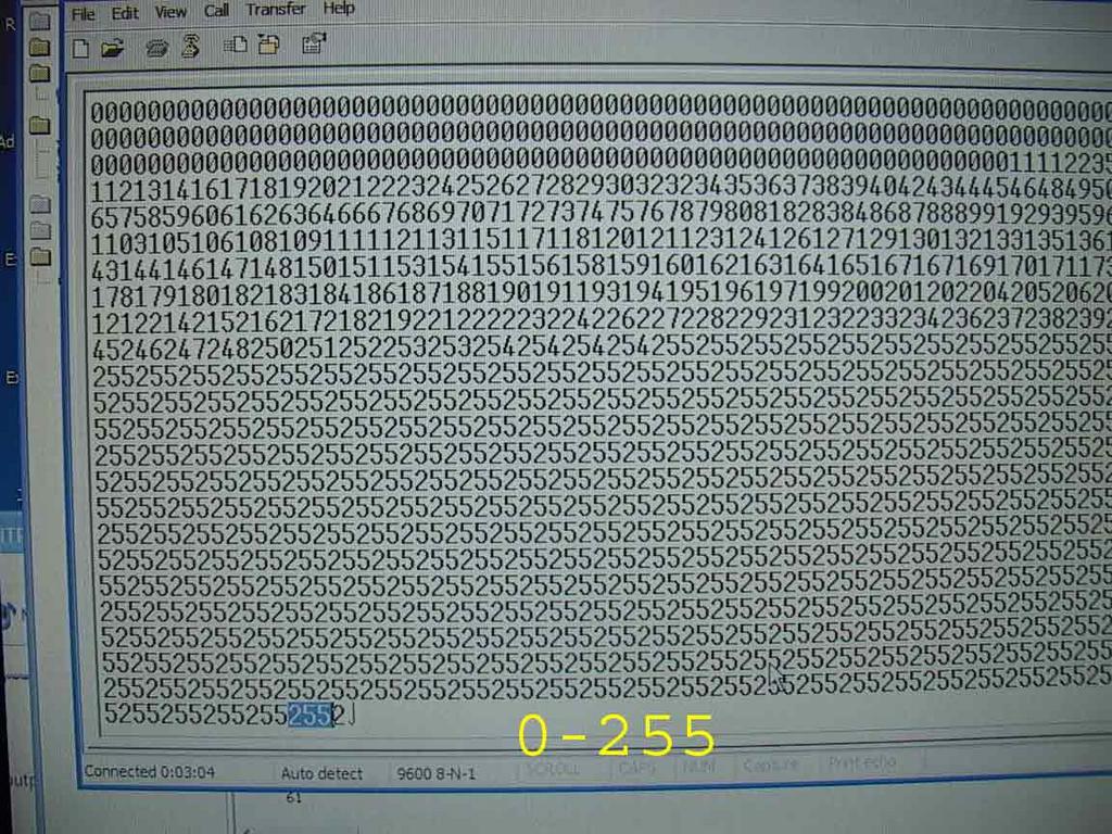
ADCIN 0, ADCvar
' Read channel 0 to adval
'ADCvar = ADCVar/4
serout2 PORTC.6, 16468, [DEC ADCvar, 13, 10]
' print it to serial out, '
' with linefeed and carriage return (10, 13)
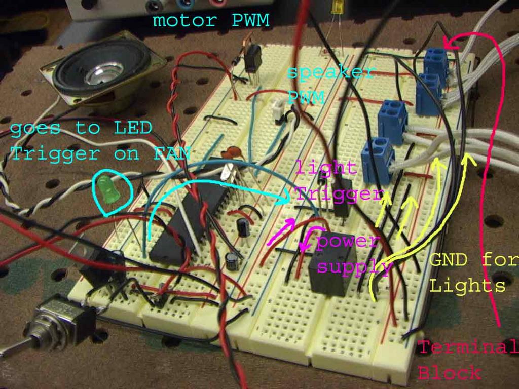
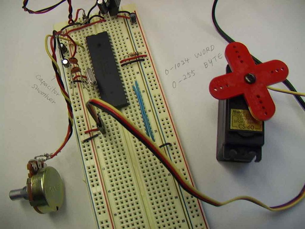
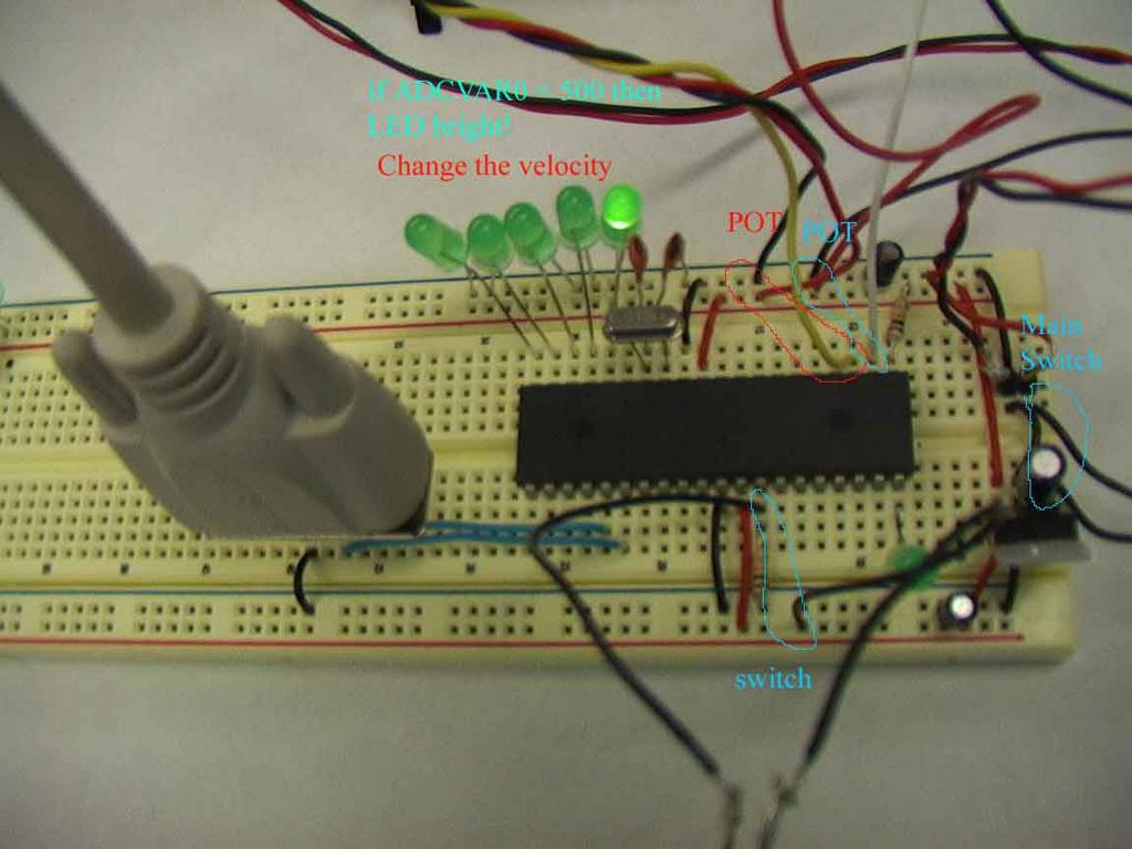
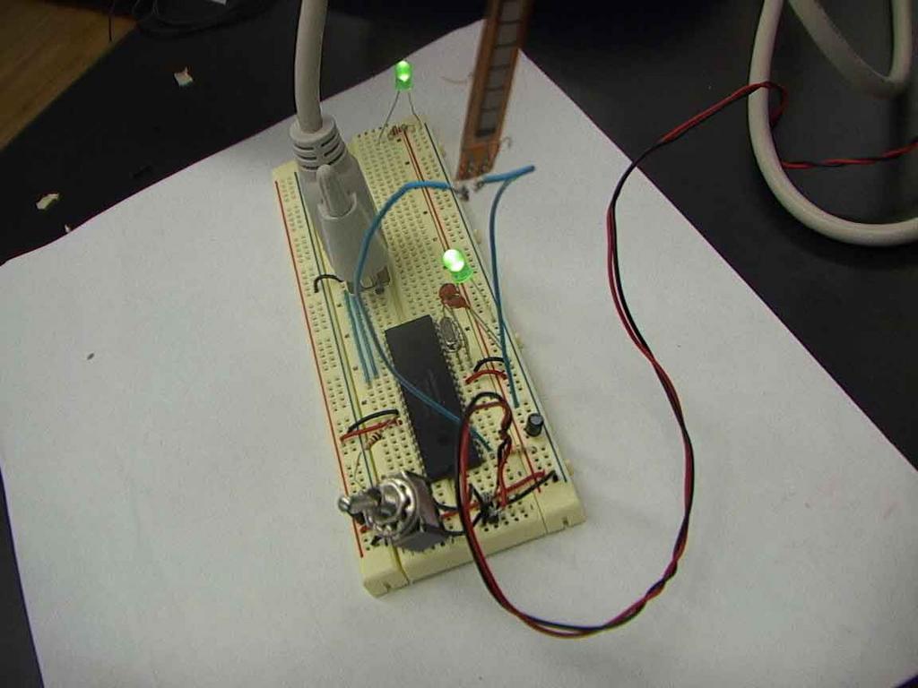
'If I stay closer to the FAN, the FAN will start to rotate,
'simultaneouly speaker, lighting trigger too.
if ADCVar >= 100 then
HIGH portb.7
HIGh portb.6
motorVal = ADCVar/8
soundVal = ADCVar/8
PWM portd.1,motorVal,10
PWM portd.0,soundVal,10
else
LOW portd.0
LOW portd.1
LOW portb.7
LOW portb.6
endif
'PWM comment ---, duty of square wave , cycle of square wave of frequency
'pwm portd.2,ADCVar,100
'Use HPWM instead of PWM, this is HARDWARE PWM.
'Put HPWM to portc.1 (Only either portc.1 or portc.2 of pic can be used for HPWM )
'This means, use HPWM into portc.2, CCP1 and use ADCvar with 1000 frequency for MOTOR
'(1000 is appropriate, sometimes 200 is possible as low frequency.)
'FREQOUT PORTd.2,2000,ADCvar*100
'This is new syntax for speaker
'This means FREQOUT into PORTd.2 as 2000 and ADCvar X 100
'(FREQOUT needs a lot of number)
GoTo main
posted by Yoshie @ Thursday, July 28, 2005
0 comments
![]()


