
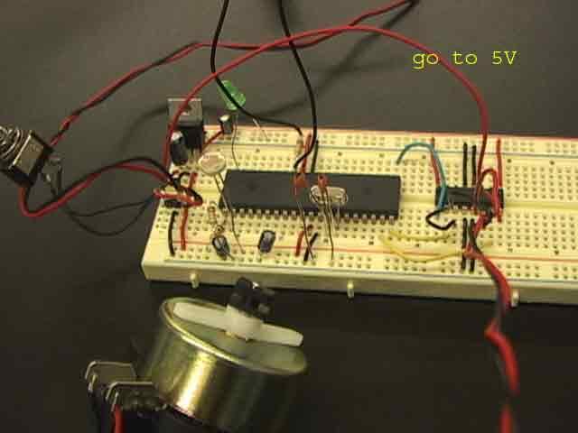
DCMotor Control Pot Photocell
'"When the switch is on, the motor is going to rotate."
' Set the motor (see page258) and the switch into portb.0
' this means switch
input portb.0
' This means information for motor rotation
' because motor is connected by portd.0 and portd.1
output portd.0
output portd.1
main:
'loop
'If the switch is on, then...
if portb.0 = 1 then
'Motor is going to rotate
'make pin 1 (=portd.0) high
high portd.0
'make pin 2 (=portd.1) low
low portd.1
'Otherwise motor is stopped.
else
'make pin 2 high
LOW portd.1
'make pin 1 low
LOW portd.0
'if I want to make the motor is going to rotate backwards, I say
'LOW portd.1
'HIGH portd.0 (but this can't rotate backwards)
endif
'end loop
goto main
-------------------------------------------------------------------------
'"Make the switch stop with dialing Pot"
'set pot into AN0
' OSC=Oscirator 4mhz
' It's not necessary but recommended
DEFINE OSC 4
start:
'This is Analog INPUT definifition
DEFINE ADC_BITS 10
' Set number of bits in result
DEFINE ADC_CLOCK 3
' Set clock source (3=rc)
DEFINE ADC_SAMPLEUS 50
' Set sampling time in uS
ADCvar VAR word
' Create variable to store result
TRISA = %11111111
' Set PORTA to all input
ADCON1 = %10000010
' Set PORTA analog and right justify result
' this means switch
input portb.0
' This means information for motor rotation.
output portd.0
output portd.1
'Set LED into portd.7 and know where pot is dialed now.
output portb.7
main:
ADCIN 0, ADCvar
' Read channel 0 to adval
ADCVar = ( ADCvar / 17)
'loop
'If the switch is off
'if ADCVar <= 125 then
high portb.7
'make LED high
'These mean for motor
high portd.1
'make pin 1 low
low portd.0
'PWM comment ---, duty of square wave , cycle of square wave of frequency
pwm portd.2,adcvar,100
'else'
low portb.7
'make pin 2 high
'These mean motor stops
'low portd.1
'make pin 1 low
'low portd.0
'endif
'end loop
GoTo main
--------------------------------------------------------------------------
''Photocell & 10K ohm are always together."
'set photocell into AN0 (Usually need 20 ohm resistor with photocell)
'photocell-can work as a sensor for the lightness.
'OSC=Oscirator 4mhz (crystal, capasitor)
'This define is not necessary but highly recommended
DEFINE OSC 4
start:
'This is Analog definifition
DEFINE ADC_BITS 10
'Set number of bits in result
DEFINE ADC_CLOCK 3
'Set clock source (3=rc)
DEFINE ADC_SAMPLEUS 50
'Set sampling time in uS
'This is necessary for Analog INPUT = photocell
ADCvar VAR word
'Create variable to store result
TRISA = %11111111
' Set PORTA to all input
ADCON1 = %10000010
' Set PORTA analog and right justify result
' this means switch (This is not working right now.)
input portb.0
' This means information for motor rotation.
'See motor is connected to portd.0 and portd.1
output portd.0
output portd.1
'how to know where pot is
'(Set LED into portb.7 and see where I am with dailing pot or shut the light for photocell.)
output portb.7
main:
'Analog Syntax (Sensor) IN
ADCIN 0, ADCvar
' Read channel 0 to adval
' serout2 PORTC.6, 16468, [DEC ADCvar, 13, 10]
' print it to serial out, '
' with linefeed and carriage return (10, 13)
'Try to change /"17" or another number for use divided and see the motor motion
ADCVar = ( ADCvar / 17)
'loop
'If the switch is off
'Just in case, <=, instead of only, <
high portb.7
'makes portb.7 high (LED)
'These mean for motor
high portd.1
low portd.0
'In order to use PWM, I need this statement.
'PWM comment ---, "duty" of square wave of frequency, "cycle" of square wave of frequency
pwm portd.2,ADCVar,100
'else
'low portb.7
'make pin 2 high
'These mean motor stops
'low portd.1
'make pin 1 low
'low portd.0
'endif
'end loop
GoTo main
posted by Yoshie @ Saturday, July 16, 2005
![]()
0 Comments:
Post a Comment
<< Home